 |
Pages: « ... 7, 8, 9, 10, 11, 12, 13, 14, 15, 16, 17, 18, 19, 20, 21, 22, 23, 24, 25, 26, 27 ... » : All |
   |
|
 Author Author |
 Right - join Part A to Part B etc, etc, etc (currently 14,512 views) Right - join Part A to Part B etc, etc, etc (currently 14,512 views) |
| Brian |
| Posted on: July 22nd, 2013, 15:41:22 |
  |
|
Big Member

Location: San Mateo, CA, USA
Posts: 330
Reputation: 0 (tot: ) |
|
For the heated screen switches...are you running a relay? For the larger draw items such as heaters, headlamps, etc, it will be better to run a relay. For the screens, some suggest a timed relay which will automatically turn off after 10 or so minutes.
I was unable to find the power draw for the window heaters. But the seat heaters I plan to use (in lieu of a standard heater) take 10 amps (well, a 10 amp fuse, so probably 8ish amps) . The switches seem to usually have ratings in the neighborhood of 10 amps, too, so it should be fine. I still just plan to power a relay with the switch, though. It will be far easier to swap a burnt relay module from the fuse box than to take the dash apart to fix a switch. And, it means a much smaller gauge of wire that I need to pull into the dash (at least for rear screen). |
|
|
|
 |
Reply: 240 - 599 |
|
 |
| Simon Robinson |
| Posted on: July 22nd, 2013, 20:16:01 |
|
|
Big Member

Location: Northampton
Posts: 338
|
|
I'd certainly say you need a relay for the rear screen at least - it draws around 15-20A and a timer relay helps if you forget to switch it off!
Be careful with the heated front screens, they only use a low current and can easily burn out a few wires, which then adds more load to the others... |
D&H Mk IV 8313, KGV 215V (aka George) - 75,000 miles and counting since restoration in 2011. |
|
|
|
| |
Reply: 241 - 599 |
|
|
| Brian |
| Posted on: July 22nd, 2013, 20:27:29 |
|
|
Big Member
Location: San Mateo, CA, USA
Posts: 330
Reputation: 0 (tot: ) |
|
Simon, I didn't follow your comment re: the front screen. I presume you were suggesting that some of the individual heating element wires can burn out...it doesn't seem that there would be much to do to do to prevent this...?
|
|
|
|
| |
Reply: 242 - 599 |
|
|
| Brian |
| Posted on: July 23rd, 2013, 01:36:52 |
|
|
Big Member
Location: San Mateo, CA, USA
Posts: 330
Reputation: 0 (tot: ) |
|
“ |
Quoted from admin, posted July 20th, 2013, 16:12:14 at here |
” |
The channels on the floor pan are for the brake line and fuel line. The usual path for the battery cables is through the sill on the left hand side for right hand drive, so the battery is at the left rear. I'd take the earth cable through the bulkhead to terminate on the engine e.g. using one of the thermostat cover studs. Then I connect earthing cables from the electrics at the front of the car to the engine block on each side. At the back the lights, fuel tank and pump (if fitted) can be earthed directly to the battery terminal.
|
|
I had been thinking of this: "The battery cable, taken from the donor vehicle, should be fitted into the channel moulded into the passenger side of the car and secured every 30-40 cm." from the build manual.
According to the manual, you do the driver's side channel for brake+fuel, and the passenger side one for power. However, in his case, if going with the 3 fuel pipes for a SPi/MPi, then I guess that takes some extra space... |
|
|
|
| |
Reply: 243 - 599 |
|
|
| Brian |
| Posted on: July 23rd, 2013, 01:40:07 |
|
|
Big Member
Location: San Mateo, CA, USA
Posts: 330
Reputation: 0 (tot: ) |
|
“ |
Quoted from admin, posted July 20th, 2013, 16:12:14 at here |
” |
I have thought about using a bus bar because I happen to have one from a telephone exchange but I didn't see how it would be fitted. It's got short wires coming out at regular intervals on one side for connecting things to.
|
|
The bus bar I was talking about were equivalent of the terminal blocks here:

http://www.vehicle-wiring-products.eu/VWP-onlinestore/connectors/connectors.php
They have various sizes depending on amperages. But a small one like that makes it far easier to add and remove grounds for things such as lights, gauges, etc without having to gang them up on a single post.
I would stick one of these in the dash, one in the back area near the tail lights, probably one in the engine bay (though those items can also ground to the subframe), and in my case, I may have a fair bit of electronic stuff, with seat heaters, etc, in the cab, so one additional one behind the driver's seat if I can find a good place for it. |
Last modified July 23rd, 2013, 01:44:35 by Brian |
|
|
|
| |
Reply: 244 - 599 |
|
|
| Simon Robinson |
| Posted on: July 23rd, 2013, 05:44:56 |
|
|
Big Member
Location: Northampton
Posts: 338
|
|
| Brian - I'm not sure what can be done either, just thought it best to let you know as quite a bit of my heated screen no longer works! |
D&H Mk IV 8313, KGV 215V (aka George) - 75,000 miles and counting since restoration in 2011. |
|
|
|
| |
Reply: 245 - 599 |
|
|
| Brian |
| Posted on: July 23rd, 2013, 07:37:10 |
|
|
Big Member
Location: San Mateo, CA, USA
Posts: 330
Reputation: 0 (tot: ) |
|
| Ah, fair enough. I'll ask around here for advice. (dad is an electrician). Will note it in the forums here if I get any input. |
|
|
|
| |
Reply: 246 - 599 |
|
|
| Graham Bichard |
| Posted on: August 4th, 2013, 16:33:43 |
|
|
Maximum Member2


Posts: 751
|
|
Latest progress - I've split the live and earth cables:
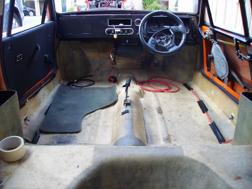
I've also tried to tuck the loom up under the LH door. This would only work if a carpet can be made to sit correctly.
While I had the car out in the sun I did notice the rather large gap between the door and the door glass:
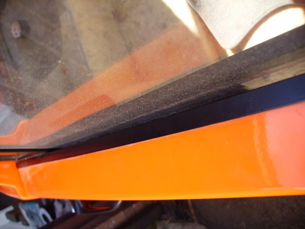
I take it there's a solution to this? (Modify the mini door rubber?) |
|
|
|
| |
Reply: 247 - 599 |
|
|
| Graham Bichard |
| Posted on: August 4th, 2013, 16:40:23 |
|
|
Maximum Member2
Posts: 751
|
|
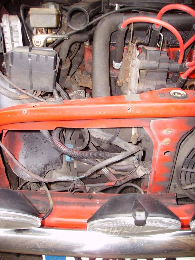
The next step is to drill through the bulkhead to get the earth to the engine compartment. I had thought using a coach bolt type screw (i.e. shallow rounded head to sit flush to the floor) at the lower 'red dot' position:
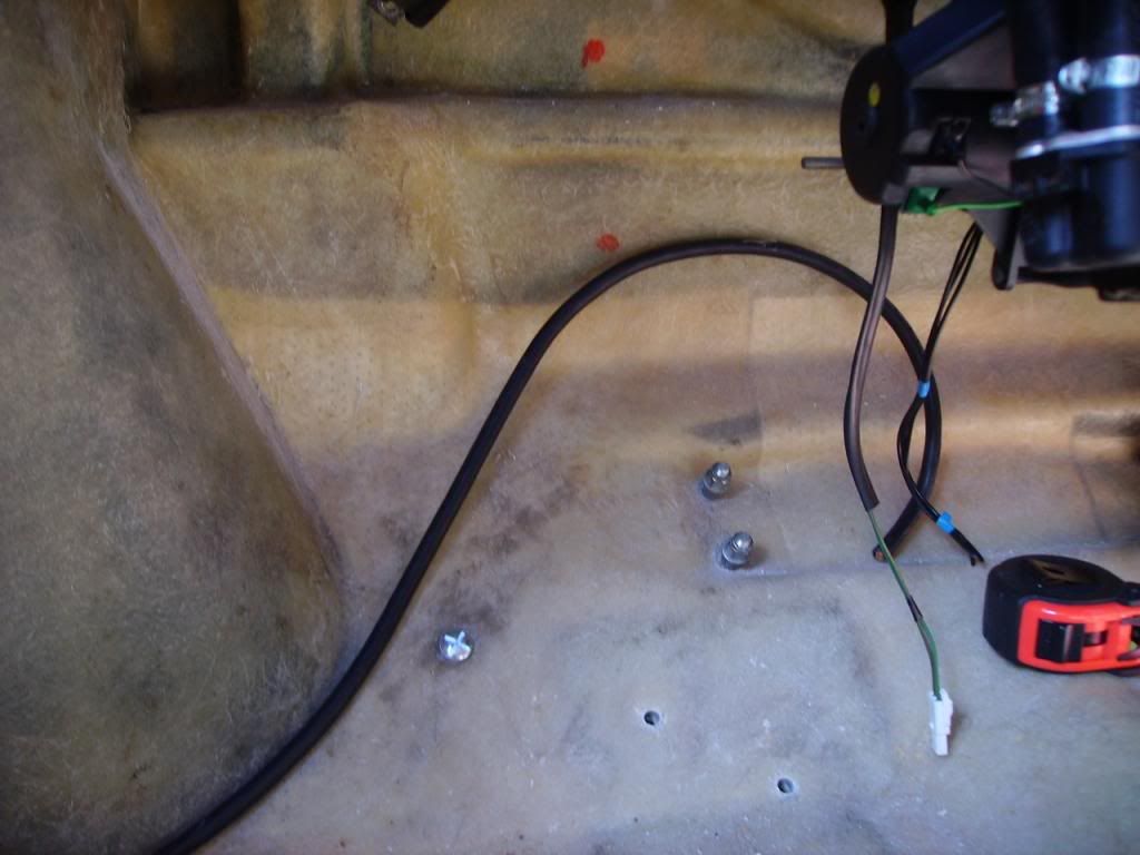
From offering up the seats, this would be pretty clear of the passengers seat and clear of the subframe/fuel pipes/exhaust etc on the other side. It would also be convenient for running the earths down from behind the dash. Any thoughts on this solution? |
Last modified August 4th, 2013, 16:40:50 by Graham Bichard |
|
|
|
| |
Reply: 248 - 599 |
|
|
| Peter Bremner |
| Posted on: August 5th, 2013, 21:21:28 |
|
|
Big Member

Location: Ongar, Essex
Posts: 410
|
|
| Hello, how about a length of studding? A washer on each side against the glassfibre, then a nut and spring washer each side done up tight, then you will have an earth post on either side. Demon Tweeks etc do a proper (expensive!) bulkhead connector which amounts to the same thing. |
|
|
|
| |
Reply: 249 - 599 |
|
|
| Graham Bichard |
| Posted on: August 6th, 2013, 11:59:21 |
|
|
Maximum Member2
Posts: 751
|
|
| I like your thinking Peter, and I have some 8mm stud too! |
|
|
|
| |
Reply: 250 - 599 |
|
|
| Graham Bichard |
| Posted on: September 8th, 2013, 19:09:37 |
|
|
Maximum Member2
Posts: 751
|
|
Okay - so I've made a little progress. I've put a stud on the passenger side for the neg's, and one on the drivers side to take the pos through to the engine compartment. (I thought I had a pic but discover I haven't).
I have managed to sort out the front subframe, rear mounts though:
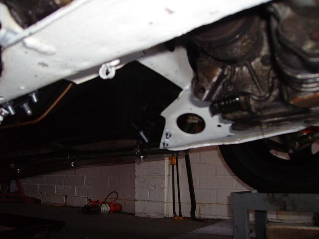
When I say sorted - the moving of the car in and out of the garage plus jacking it up to put on the ramp stands must've settled things down because, with only a little elongating of the mount holes the subframe mounts were pretty close. Happy days! (You might notice all the nut are plain nuts. I'll replace these with nylocs after the strip down and final build).
I've also fitted the starter motor. Am I correct in thinking this is what I want to be putting the direct battery feed to? (I really need to re-read John's electric book).
Is there a prefered position/method of earthing the engine and subframe - what do you attach the cable to for best effect?
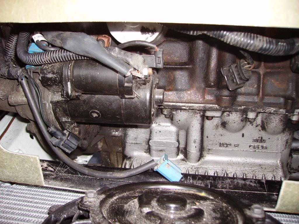
This is the view I'm using for comparison:
 |
Last modified September 8th, 2013, 19:11:23 by Graham Bichard |
|
|
|
| |
Reply: 251 - 599 |
|
|
| Graham Bichard |
| Posted on: September 22nd, 2013, 12:10:57 |
|
|
Maximum Member2
Posts: 751
|
|
Did a little bit of sorting of the Rat's Nest wiring, comparing the mini with the MM loom yesterday. Also got around to making up the cable from the bulkhead to the starter motor.
Simon - have you got a wiring diagram of how you wired in your heated front screen (I think you might have posted something previously but I haven't been able to find it)? Where did you take the low current supply from? If you've had elements burn out is there another supply you'd recommend trying?
Brian, heated seats! Luxury  |
|
|
|
| |
Reply: 252 - 599 |
|
|
| Brian |
| Posted on: September 22nd, 2013, 15:33:19 |
|
|
Big Member
Location: San Mateo, CA, USA
Posts: 330
Reputation: 0 (tot: ) |
|
The low current supply will want a switch on the dash. I'd run a wire from the back of the ignition to toggle switch to relay. That way it turns off with the car.
|
|
|
|
| |
Reply: 253 - 599 |
|
|
| Brian |
| Posted on: September 22nd, 2013, 18:35:30 |
|
|
Big Member
Location: San Mateo, CA, USA
Posts: 330
Reputation: 0 (tot: ) |
|
I was thinking about this more. The "low current" thing is something tough to control electrically.
You'll still want to use a relay to power it. Operate the relay with a wire from ignition to a toggle on the dash, then to the low power input on the relay.
For the bigger wire out of the relay, you do input to the relay from a big wire, possibly the battery cable. Fuse it between the battery wire and the relay. As for limiting current, that's a bit tougher, but the best you'll do is to limit the voltage to it. There are a few ways I can think of, ranging in cost and complexity.
* Many older cars used smaller wire than should be used, to cause a voltage drop over the length of the wire. For example, this is how the ignition switches in older cars worked, allowing it to get the needed 6 volts at the coil.
* If "correct" wire sizes were used for ignition instead, then a ballast resistor is needed. Similar could probably be done for the heater element. I suspect dropping the voltage to 10-12 (versus the 13-16 normally experienced when running) will help some. We'd need to know how many amps the screen draws, then pick a resistor that will drop the voltage sufficiently for that current.
* Not practical, but a 12 volt regulated power supply could be used. I use one of these http://www.opussolutions.com/shop/50/Sub_ATX_DC_DC_Power_Supplies/0.html for some radio gear in my race car that wants cleaner 12v. They take in 8 to 40 volts, and put out a clean 12 volts. But I assume the front window heater will take more than 6-10Amps.
|
|
|
|
| |
Reply: 254 - 599 |
|
|
Pages: « ... 7, 8, 9, 10, 11, 12, 13, 14, 15, 16, 17, 18, 19, 20, 21, 22, 23, 24, 25, 26, 27 ... » : All |
|
|
| |
| Forum Rules |
You may not post new threads
You may not post replies
You may not post polls
You may not post attachments
|
HTML is on
Blah Code is on
Smilies are on
|
|
|
|


 Mini Marcos Forum > General Boards > Mini Marcos > Right - join Part A to Part B etc, etc, etc
 Logged


