 |
Pages: « ... 17, 18, 19, 20, 21, 22, 23, 24, 25, 26, 27, 28, 29, 30, 31, 32, 33, 34, 35, 36, 37 ... » : All |
   |
|
 Author Author |
 Right - join Part A to Part B etc, etc, etc (currently 26,945 views) Right - join Part A to Part B etc, etc, etc (currently 26,945 views) |
| Graham Bichard |
| Posted on: May 2nd, 2016, 17:20:09 |
  |
|
Maximum Member2


Posts: 751
|
|
So, cashed in some brownie points and spent some money this past couple of weeks.
A new lambda fitted to the new centre branch:
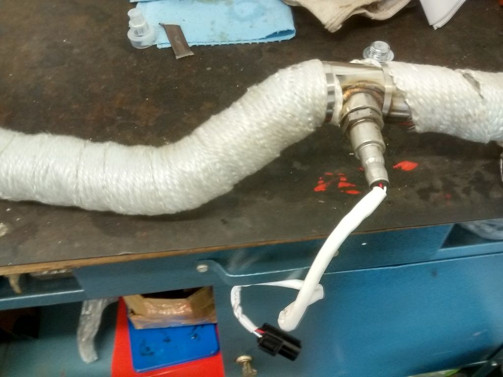
This new centre branch had a thinner flange than the outer 'Y' so I had to make up a couple of T-pieces to ensure the inlet/exhaust were equally clamped:
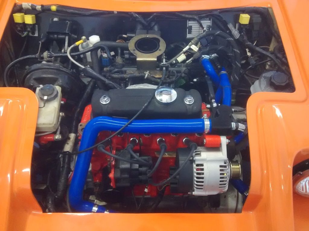
With this all tightened up I could fit the new alternator:
I've got an MPi alternator belt but it's just too tight, so I still need to source a longer belt for this.
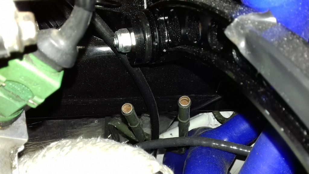
I've managed to connect up the hard pipe for the brake master cylinder, also the clutch, but I couldn't get the fuel connections onto the fuel pipes:
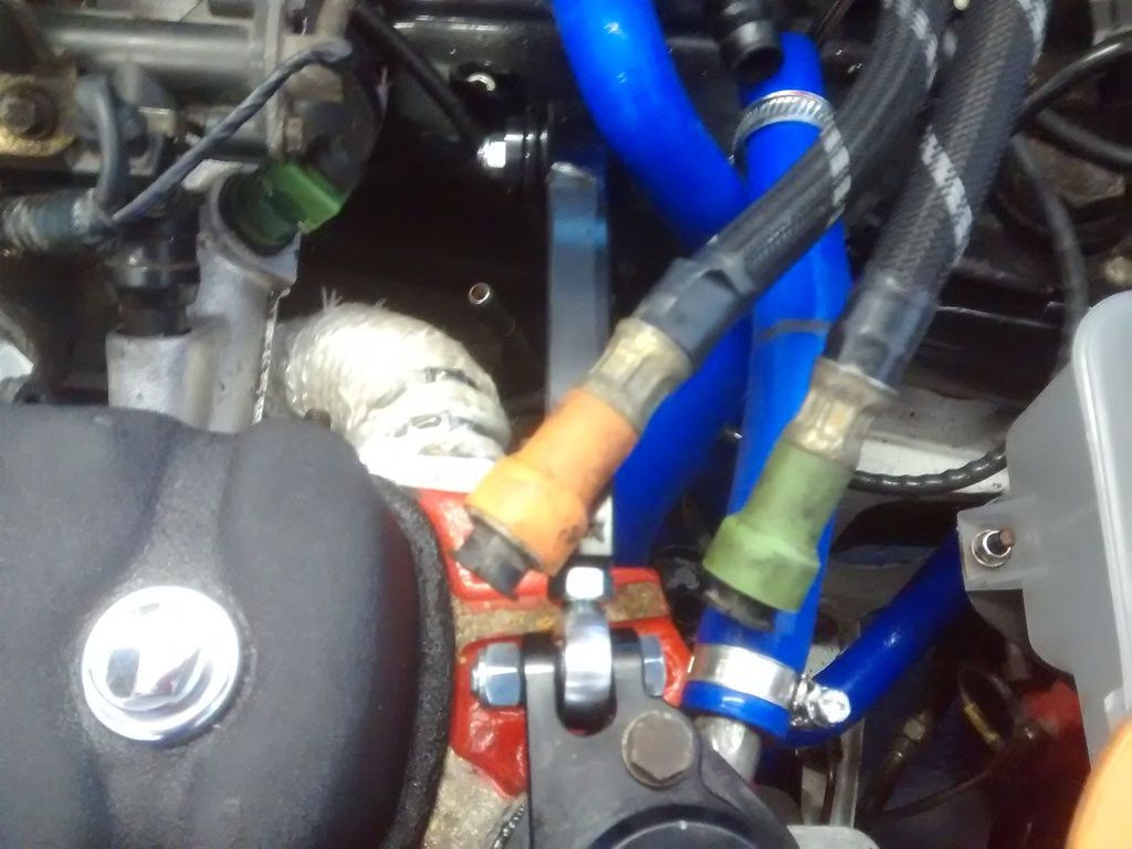
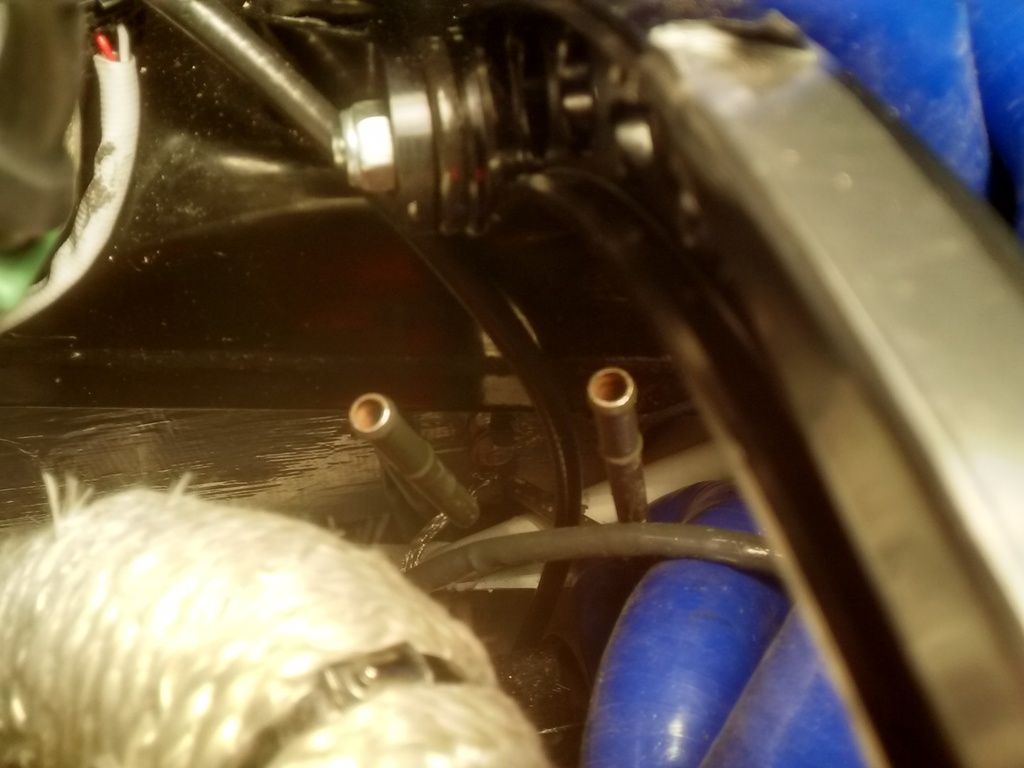
The charcoal pipe is just a push on, but I'll be damned if I can get these to click into position (as on my MPi). The idea of using original pipes was to make things simple, but this is just a pain!
I could cut the connection off and plumb straight to the hard pipe, but what kind of clamp would secure this (fuel is approx. 2 Bar pressure I think).
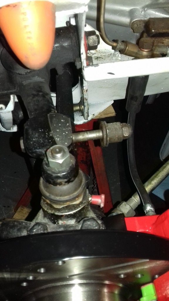
So I moved the car in the garage to enable me to work on the brakes. I thought I'd offer up the front right damper. Unfortunately the lower mount bolt isn't long enough (or at least it's not long enough in this application):
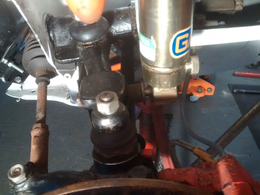
What thread/size is this bolt, so I can source a new one?
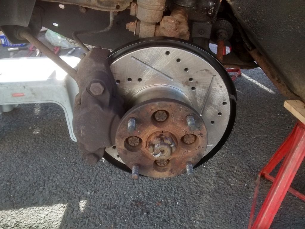
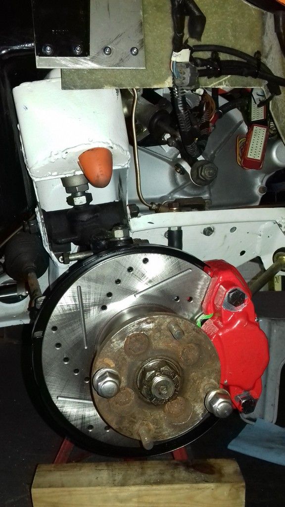
And I dug out the old solid disc set up so I can swap the flanges:
[URL=http://s221.photobucket.com/user/Cooper1999/media/20160502%20Solid%20disc_zpsewb1mlel.jpg.html]
I also discovered I'm going to need a bespoke throttle cable - the MPi one I have doesn't have enough movement. The inner needs to be about 3" longer.
So time to stop spending for a while and start fitting the other bits and pieces I have now. |
|
|
|
 |
Reply: 390 - 599 |
|
 |
| jimnaylor |
| Posted on: May 3rd, 2016, 20:24:32 |
|
|
Big Member


Location: Bedfordshire
Posts: 222
|
|
|
|
|
| |
Reply: 391 - 599 |
|
|
| Graham Bichard |
| Posted on: May 28th, 2016, 13:12:06 |
|
|
Maximum Member2
Posts: 751
|
|
Jim, I suspect you're right.
I fitted one of these top mounts but not the other. If this is the one I fitted (I can't remember if it was NSF or OSF) I'll not be too happy - why would I not have offered up the damper? but I'll look to take this off, fill the holes (fibreglass and remount.
Looking at it I am a little concerned that the top mount cannot move too much rearwards due to the piece its mounted to being very short. I'll try and get a photo showing what I mean.
Progress has slowed recently. I serviced the mini a few weekends ago and discovered that one of the calliper pistons had seized, so the disc, backing plates and callipers were destined for the mini:
Unfortunately I then wasn't very well so put the mini into the garage to have the callipers swapped only to find out the drivers side calliper, when filled and trying to bleed was porous (garage thinks when these were refurbished whoever was doing it might have been a bit enthusiastic with the shot blaster). So I've been in contact with the supplier and am arranging for a replacement calliper to get the mini back on the road.
Then it'll be save up and repeat the exercise with the Marcos.
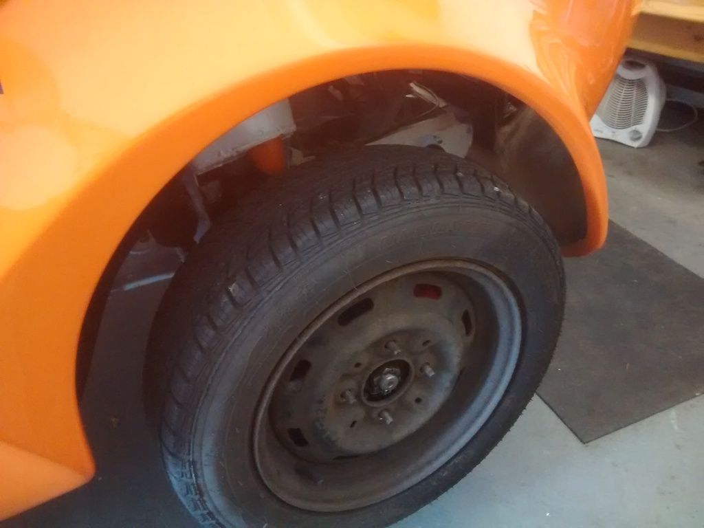
And I guess I'll be fitting the winter tyres for the IVA test:
 |
|
|
|
| |
Reply: 392 - 599 |
|
|
| Graham Bichard |
| Posted on: May 30th, 2016, 16:50:53 |
|
|
Maximum Member2
Posts: 751
|
|
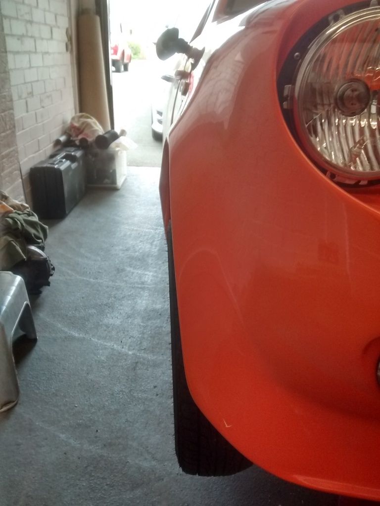
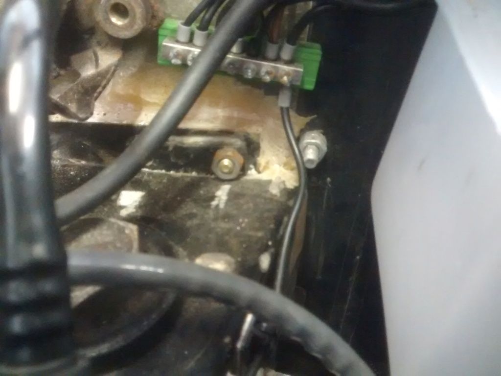
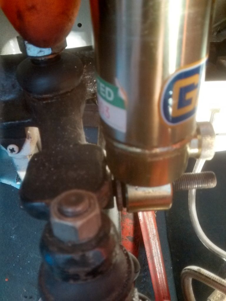
So, Here's the top mount as fitted:
Now with this undone I fitted the damper (lower end tightened up to see where the upper end sat naturally. There was some fore/aft movement but this is the situation:
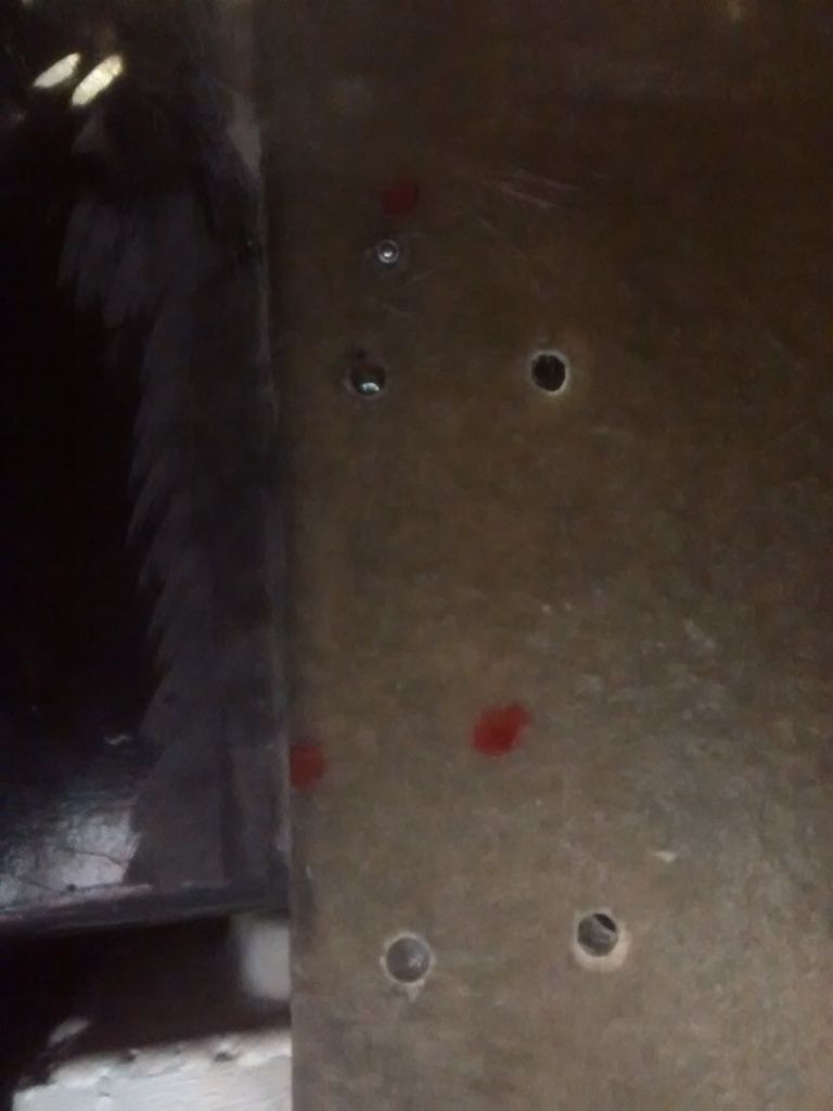
With the damper fully extended the red dots denote the mount holes.
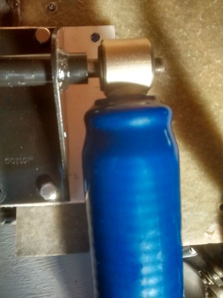
With the dampers approx. mid stroke (that is at a similar height of damper mount as the existing position) the holes are in the 'black' position:
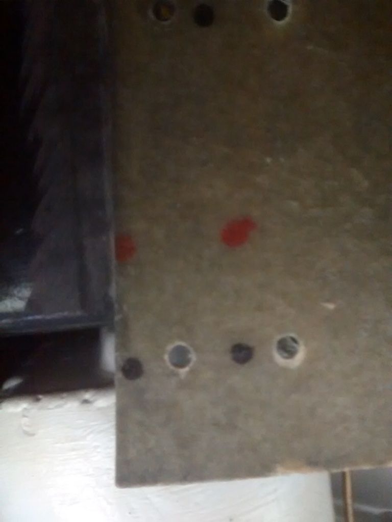
This is what I mean about the holes being very close to the edge of the 'inner wing' rear edge.
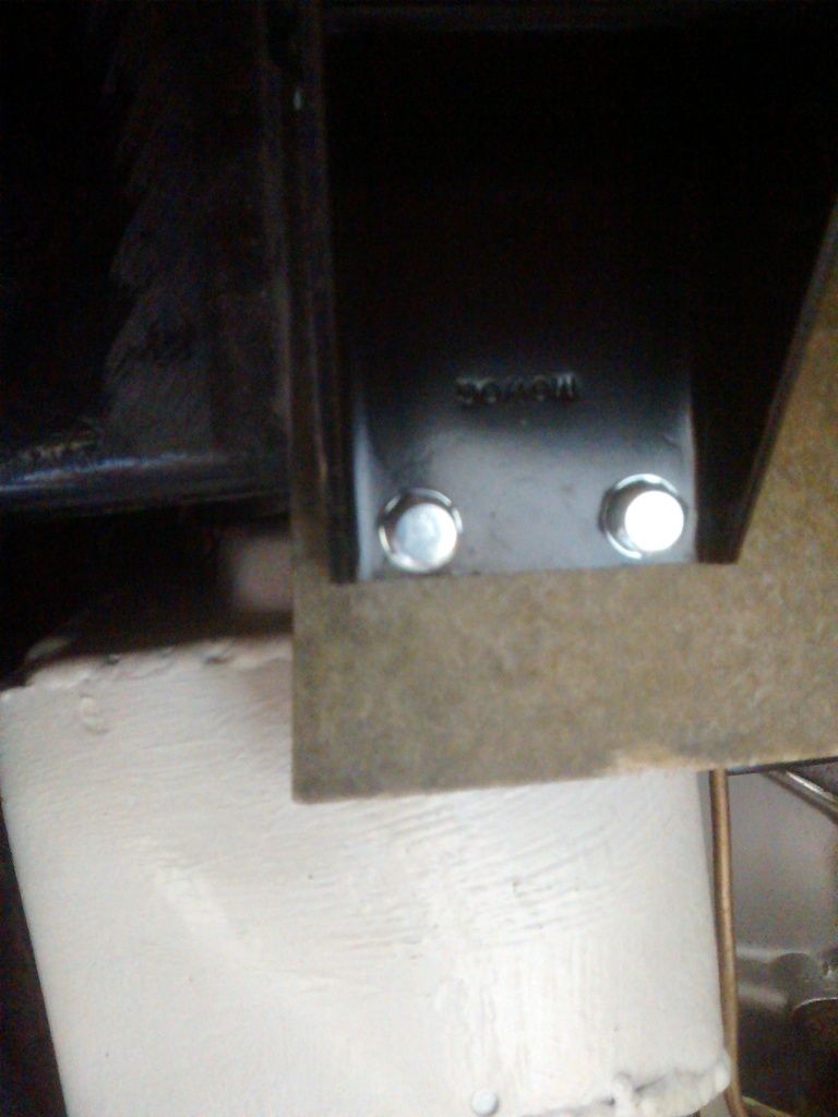
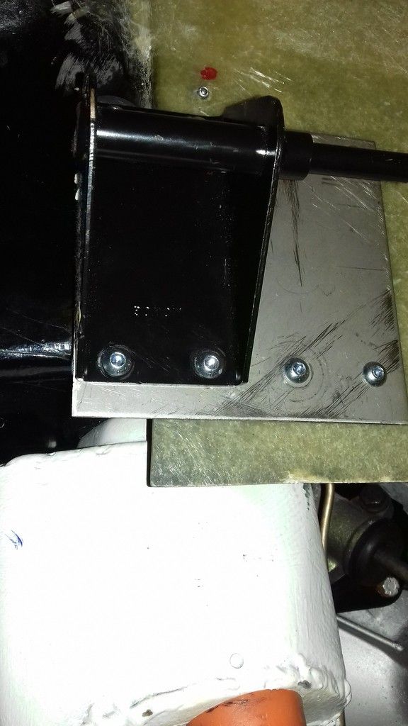
When I undid the top mount bolts I noticed these metal blocks, which have two holes which appear to match (hole centres) with the mount.
These are on both sides. From left:
From right:
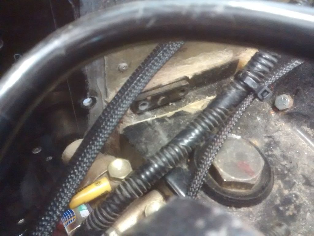
Front left shows the mount rear bolt fits through the block forward hole (the same situation can be seen in the front right block, bolts removed obviously).
So - are these blocks for the top mount bolts? Is the 'black dot' too close to the rear edge of the 'inner wing'?
What's on your cars? What should I do?
ETA - meant to ask, any ideas for the fuel line conundrum? |
Last modified May 30th, 2016, 16:54:12 by Graham Bichard |
|
|
|
| |
Reply: 393 - 599 |
|
|
| mike brown |
| Posted on: May 30th, 2016, 19:40:16 |
|
|
Big Member

Location: Southampton
Posts: 419
|
|
How about making a metal plate for the damper bracket to bolt to then bolt the plate through the original holes.
Mike |
|
|
|
| |
Reply: 394 - 599 |
|
|
| jimnaylor |
| Posted on: June 1st, 2016, 21:03:31 |
|
|
Big Member
Location: Bedfordshire
Posts: 222
|
|
The damper brackets should bolt to the ends of the bulkhead cross member. That's where the strength is and should have the correct alignment with the subframe & suspension. Just bolting to the fibreglass is unlikely to have the strength and the alignment will be wrong. Your metal blocks in the foto might be correct, they look in about the right place and pick up the cross member. I can't compare to mine as mine are fully glassed in by the previous owner (as is the x member) and the holes are threaded so I need no nuts.
Dependant upon your suspension settings if non standard you may need different length dampers, that's why a range of lengths are available from mini specialists. |
|
|
|
| |
Reply: 395 - 599 |
|
|
| Graham Bichard |
| Posted on: January 1st, 1970, 00:00:00 |
|
|
Maximum Member2
Posts: 751
|
|
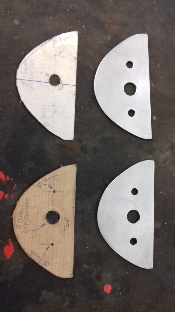
So, this is what I'm thinking.
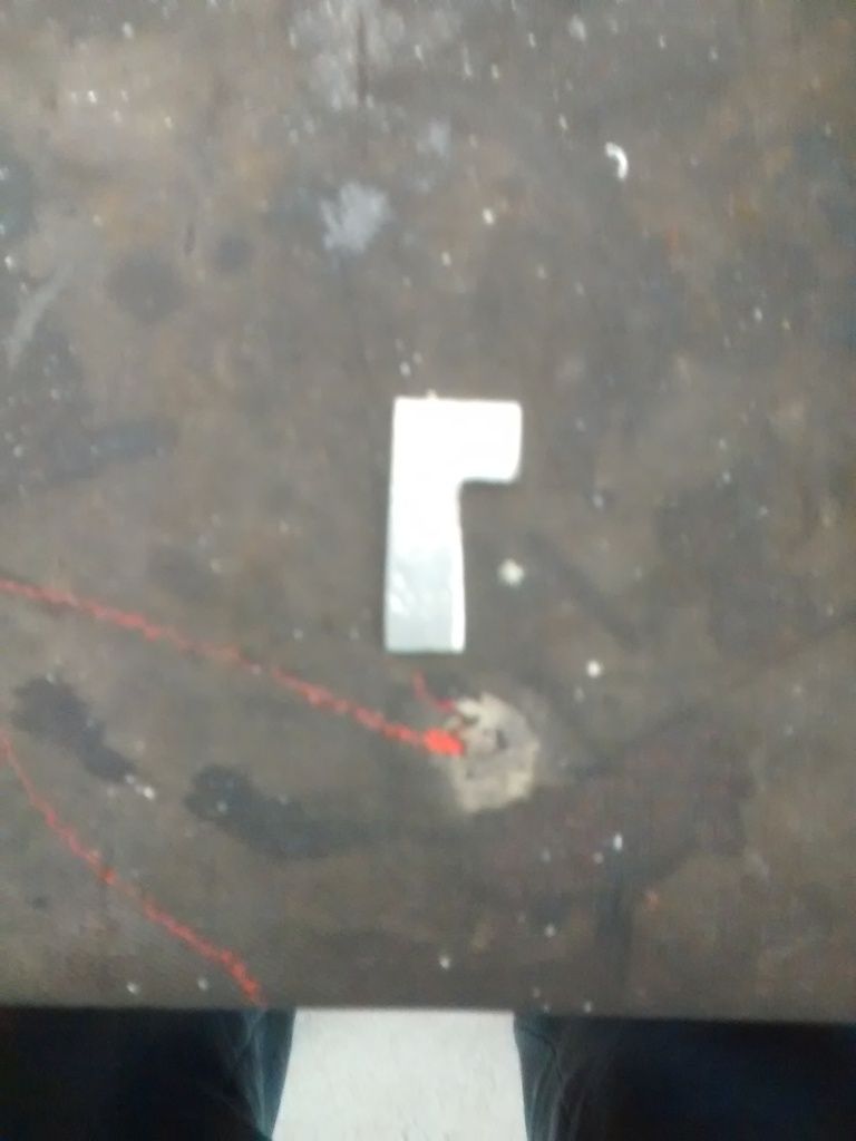
Make a metal plate as per the cardboard template in the photo:
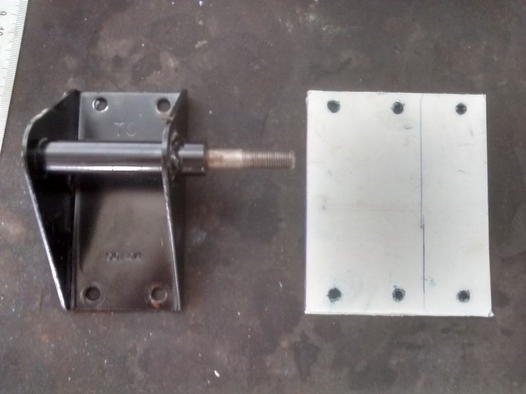
I'm thinking 2 or 3mm ali plate.
Fit the damper bracket like this:
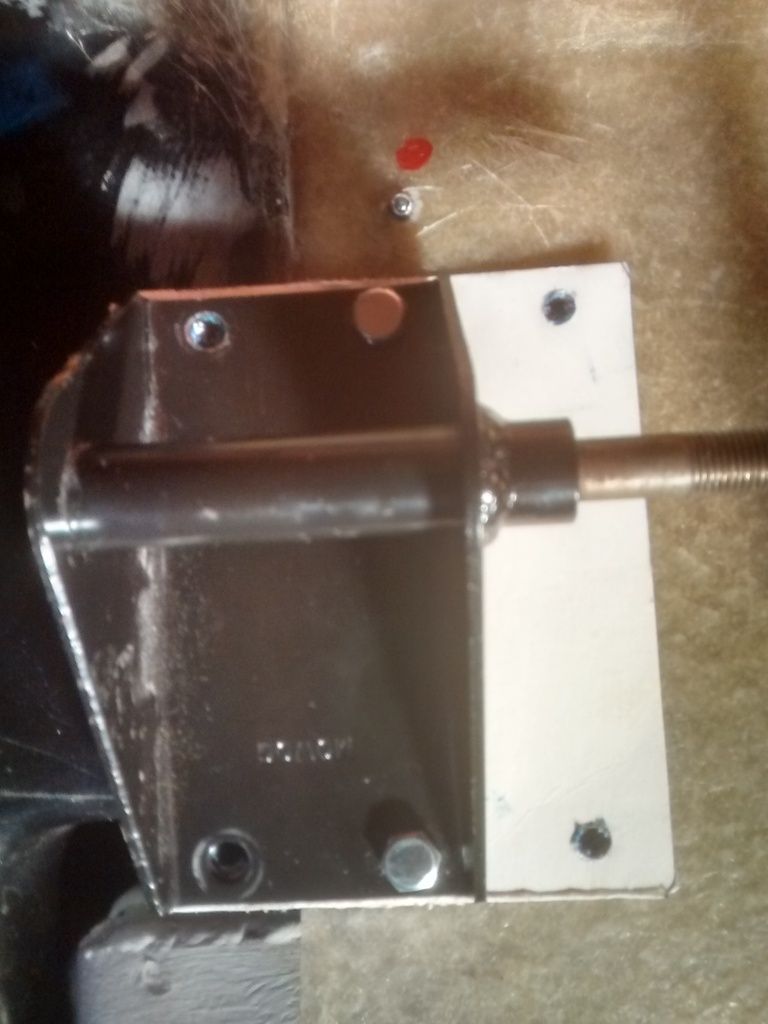
The right of the photo is the front of the car. The forward two holes will clamp the plate to the 'inner wing'. The front two bolts on the damper mount will clamp the bracket to the plate, to the inner wing.
The rear most two bolts (left side in the photo) - upper will locate in the rear most hole in the metal block, the lower will clamp the damper bracket to the metal plate.
I will need to fit washers/spacer behind the left upper bolt (gap between the plate and the inner wing)
The only other things this will result in is:
I'll need to remove the spacer piece and grind back the bump stop pad to clear the damper. And:
I'll need to make a small spacer to align the top of the damper.
Hope that makes sense. What do you think - strong/rigid enough?
What this has made me realise iscooper1999 |
Last modified January 1st, 1970, 00:00:00 by |
|
|
|
| |
Reply: 396 - 599 |
|
|
| Graham Bichard |
| Posted on: July 17th, 2016, 11:30:53 |
|
|
Maximum Member2
Posts: 751
|
|
Got an hour in the garage last night so put the first (RHF) damper strengthening plate in place:
I used Gr 10.9 zinc coated button head screws in the end as the best option to keep this in place. The titanium ones I found weren't a bad price but the equivalent of a Gr 8.8. Coating bolts can make them brittle if not done properly and I think going to 10.9 is a good compromise. The nuts are black - I've used two per screw as a locking device.
I've also used M6 coated repair washers on the rear where space permitted to spread the load. I haven't, as you can see, gone over the plate with the fibreglass/carbon fibre that I have.
When offering up the plate, the top left screw area needed to be packed out with M6 repair washers (5 used) due to the profile of the inner wing. I didn't want to trap moisture in the void and to be honest, wasn't sure how best to achieve this.
I have chamfered the upper arm to clear the damper:
And fitted the brake hose/calliper:
The damper to fit next, followed by greasing up this wheel station then onto the LHF.
One other thing - has anyone fitted the plastic wheel arch liners to their MM? I've got them fitted to the Mini and with the amount of cables, and proximity of the ECU, I'm thinking of trying to fit these to the MM to keep any water spray to a localised area. |
|
|
|
| |
Reply: 397 - 599 |
|
|
| Graham Bichard |
| Posted on: October 15th, 2016, 15:18:05 |
|
|
Maximum Member2
Posts: 751
|
|
Hi all. Been unable to get online for a little while but have been making a little progress.
Shortly after finishing the front damper mounts I was contacted by someone else building a Mk6 who had put their car through IVA, which had thrown up a few failure points.
One of which was the front damper mounts only having a flexible fibreglass fixing (glad I did the plates), so I decided to plate the rear strut top too:
I can't get the 'as fitted' photo to upload but this sits between the top of the strut and the shell.
I've also started fitting out the rear of the interior with sound proofing. It's not so pretty (I've used all the cut off sections to fill in the gaps) but it'll ultimately be covered by carpeting also (no photos at the minute).
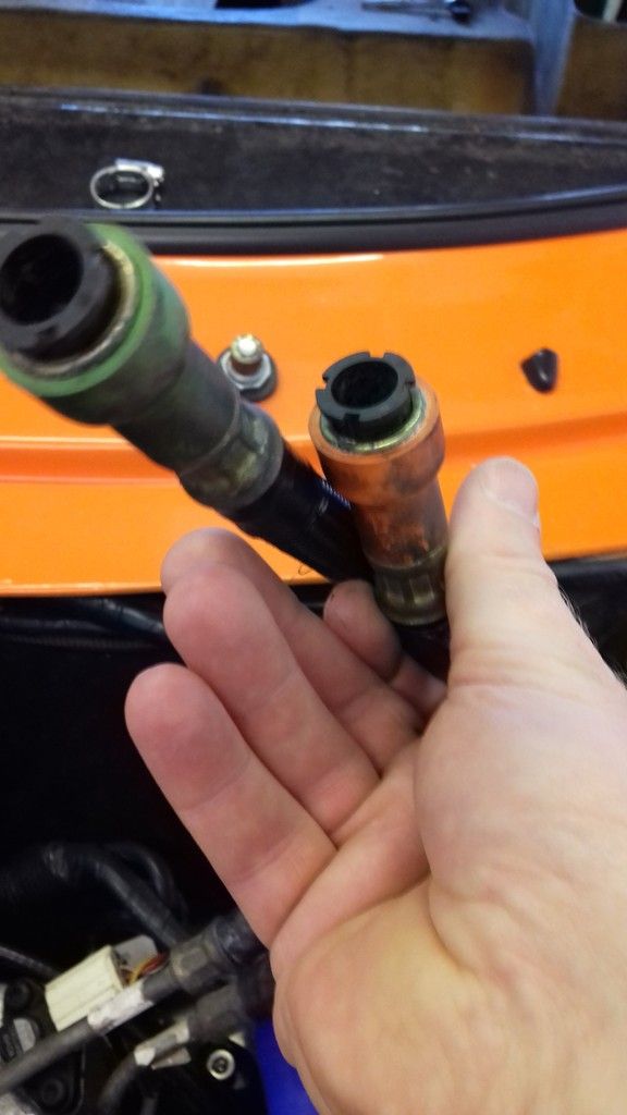
And then the problem that keeps on giving - the fuel pipes. I disconnected the fuel pipes in the mini and found that the pipes are subtly different. The 'MPI' pipes I bought off of ebay have a 'flared' end to them, with a flange about an inch down them:
The pipes on the mini have the flange but not the flared end. So after asking a lot of questions and researching it seems I've been sold SPi pipes (although it might be that very early MPi had these pipes too). As the pipes weren't working as they were I tried to smooth out the end flare.
The fit was improving but this weakened the pipe leading to:
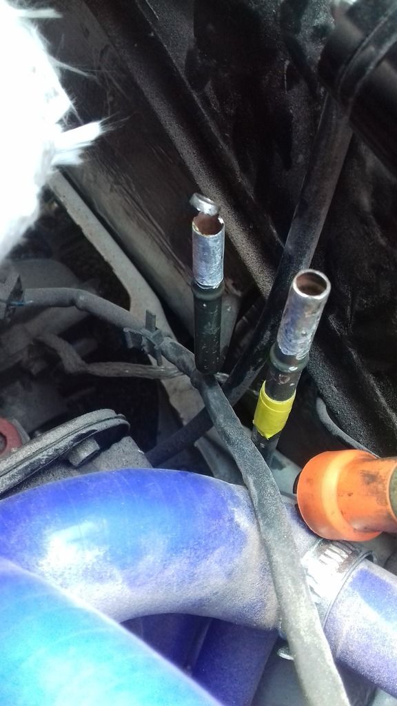
Now I can't say I'm too disappointed about this - I had my concerns over modifying these pipes and them sealing. So this has forced the situation, which is where the real problem starts.
To replace these I'll need to perhaps drop the rear of the subframe (as you do for a steering rack change), or at least I would if I could get my hands on a correct set of pipes.
I can't find another set of these for love nor money. If anyone knows of a set, please do tell!
Otherwise, if I'm to keep with the original MPI inlets, I need to find some pipework which the original flexy pipes:
Ideas welcome.
|
|
|
|
| |
Reply: 398 - 599 |
|
|
| Graham Bichard |
| Posted on: November 27th, 2016, 11:06:28 |
|
|
Maximum Member2
Posts: 751
|
|
Hi All. Well progress has been slow of late but with a long weekend this past weekend I've been able to make some progress again.
Thanks to the Rover parts bin I've managed to find a solution (I hope) to the fuel line problem. Ebay provided a Rover 25 fuel line/fuel filter pipe which has the correct push on fit:
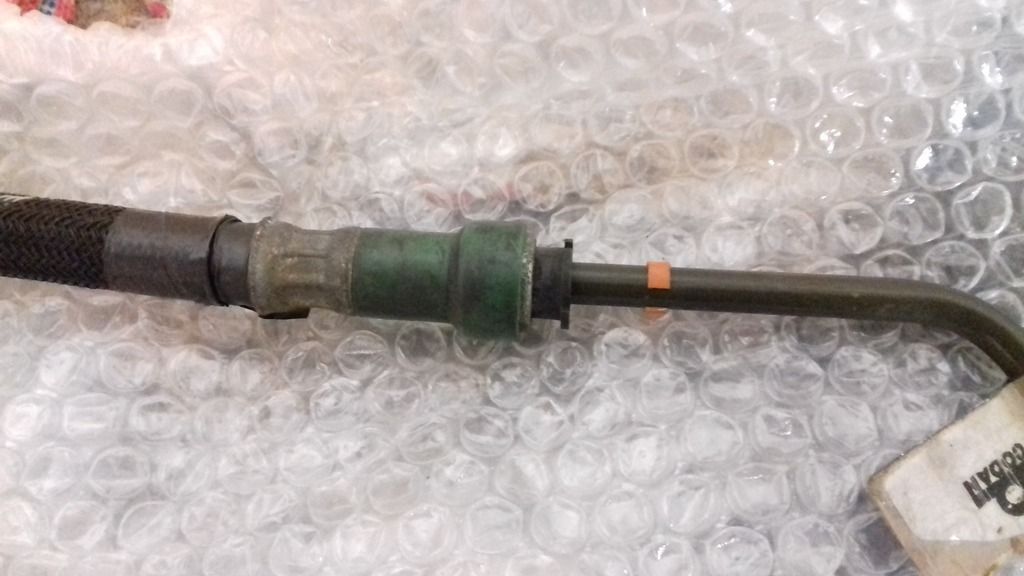
I'll cut this pipe a couple of inches long and use braided hose to connect this quick detach piece with the underfloor pipework.
Hopefully I'll be receiving another (MGF) pipe which will sort the return pipe also.
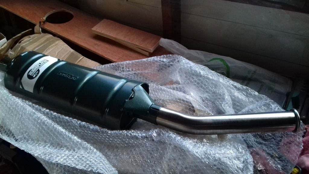
I've also received this through the post:
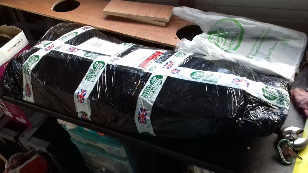
In steel (not stainless) I've gone for a two box system to try and keep the noise levels down (both for IVA and for the desire to use this car everyday and have it a bit of a GT in use). I may yet need to change this - I think I'll need to fit a cat in the system, but as with other Maniflow products I've had over the years it looks good and fits easily.
Think I'll be stealing Steve (Schmidt's) solution for an exhaust hanger!
Moving the car back and forward on the drive in order to get the car lined up with the ramps in the garage I noticed its sitting a little higher on the passenger side. This may settle down,but I'll have a look at adjusting this in the future:
 |
|
|
|
| |
Reply: 399 - 599 |
|
|
| Graham Bichard |
| Posted on: November 27th, 2016, 17:12:17 |
|
|
Maximum Member2
Posts: 751
|
|
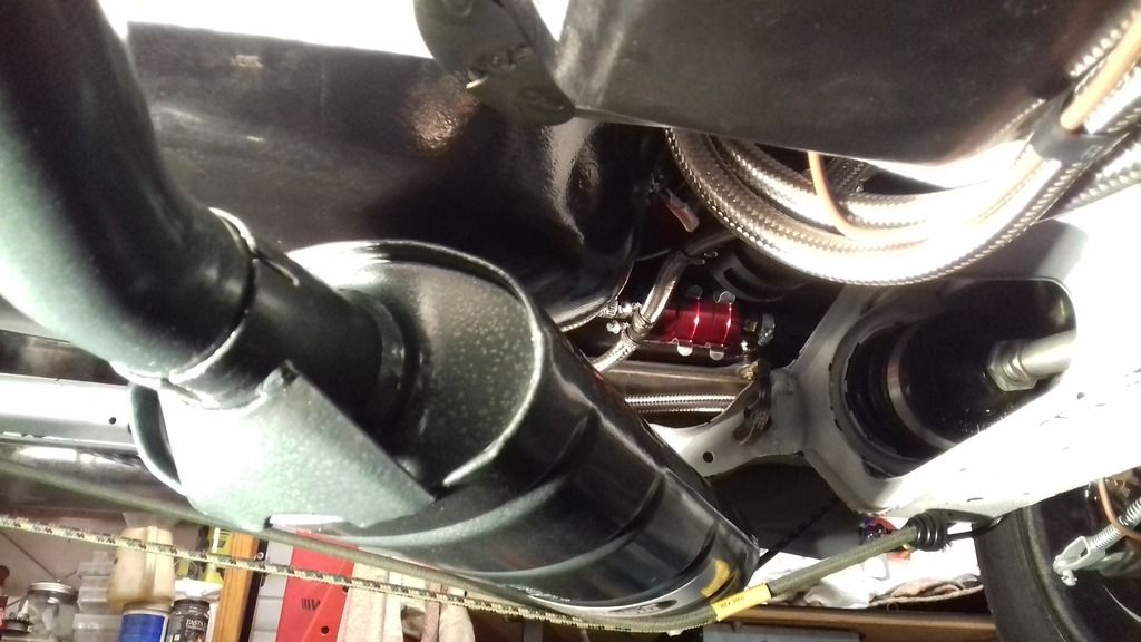
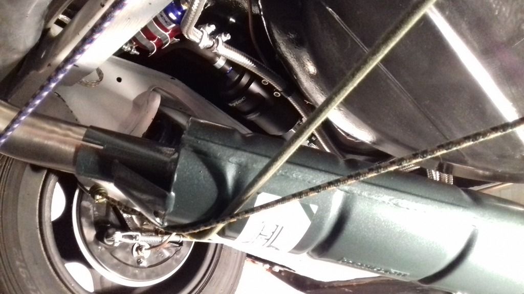
So, the exhaust can be fitted so as to exit on the left hand side or the right.
To my eyes, exiting on the left looks to have the exhaust held higher within the tunnel but does this put it too close to the fuel pump?
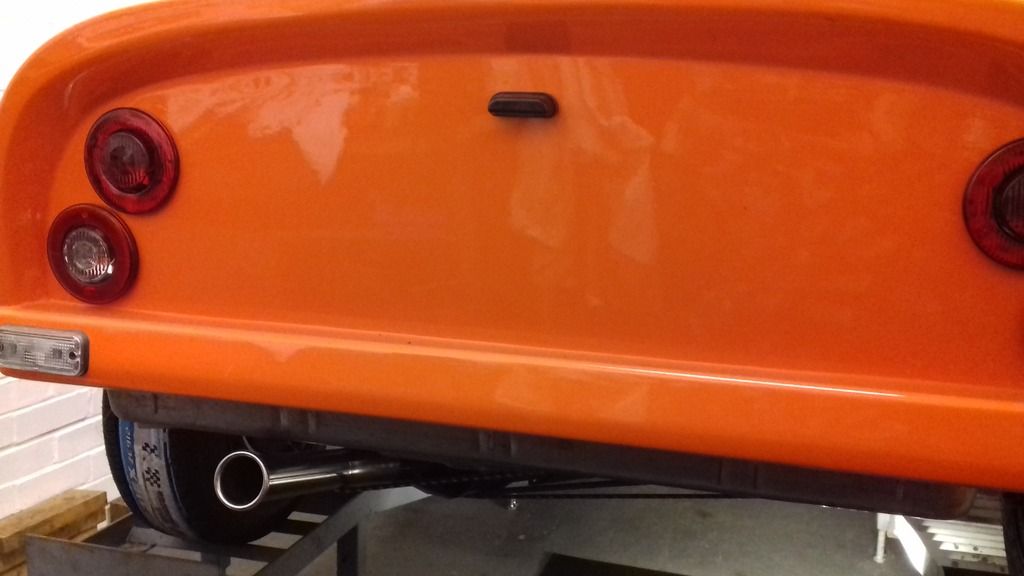
ETA Meant to ask also - what solution do you have for the lock/latch for the hatch? |
Last modified November 27th, 2016, 17:16:01 by Graham Bichard |
|
|
|
| |
Reply: 400 - 599 |
|
|
| mike brown |
| Posted on: November 27th, 2016, 17:38:35 |
|
|
Big Member
Location: Southampton
Posts: 419
|
|
Most people use a panel lock for the hatch.
Mike |
|
|
|
| |
Reply: 401 - 599 |
|
|
| Graham Bichard |
| Posted on: December 3rd, 2016, 17:17:20 |
|
|
Maximum Member2
Posts: 751
|
|
“ |
Quoted from mike brown, posted November 27th, 2016, 17:38:35 at here |
” |
Most people use a panel lock for the hatch.
|
|
Thanks Mike. I bought a mini lock set, trying to have only one key. The mini boot lock was different to the lock as fitted (with no key) and when I tried to modify it the case (which I was had drilled/tapped) failed.
Guess I'll need to be a bit more adventurous with a solution.
I have managed to track down a second fuel pipe though! I've got the week before Christmas off - what's the chances of getting it fired up...
I'll not hold my breath  |
Last modified December 3rd, 2016, 17:17:37 by Graham Bichard |
|
|
|
| |
Reply: 402 - 599 |
|
|
| mike brown |
| Posted on: December 3rd, 2016, 19:03:28 |
|
|
Big Member
Location: Southampton
Posts: 419
|
|
You maybe able to get a panel lock with the same key type and code. Failing that you maybe able to fit the mini lock barrel into a panel lock.
Mike |
|
|
|
| |
Reply: 403 - 599 |
|
|
| Graham Bichard |
| Posted on: January 14th, 2017, 21:06:33 |
|
|
Maximum Member2
Posts: 751
|
|
Happy New Year All.
Just got the computer back from repair and thought I'd give an update.
I had a bit of time off over Christmas and managed to get a bit of time in the garage. It was my intention to get it fired up and the engine bedded in. Well - I managed to get it turned over, and oil pressure built up. But couldn't get it fired up - the fuel pump wasn't (isn't) getting power now.
The pump works (fed direct off the battery) and there seems to be continuity in the cables to the bulkhead but that's where my electrical ability stops.
So I decided to do other things to progress things.
I managed to sort a panel lock for the boot (that'll be a total of four keys for the car then - boot, door, ignition and fuel cap) and decided to swap the door locks for the new ones. I did the drivers door first - what a pain in the backside that was!
Little did I know that was going to be the easy side. The passenger side door lock was surrounded by sealant. On removing this I found the door lock had a load of washers as spacers:
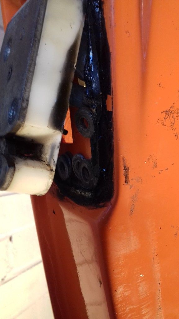
Turns out this was to place the lock in the correct position for the latch. But what a pain to get back lined up and set. I packed both lock barrels with grease. I'm hoping this will help prevent them from freezing up - a regular winter problem with the mini.
I also did some more work on the interior. I've made a boot board - this to protect/hide the wiring that runs across the back, hold the speakers, hide the battery and provide somewhere to secure a first aid kit/warning triangle:
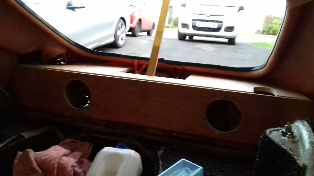
This will have a cover piece also:
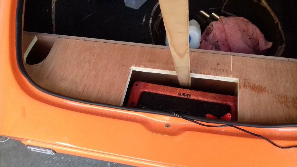
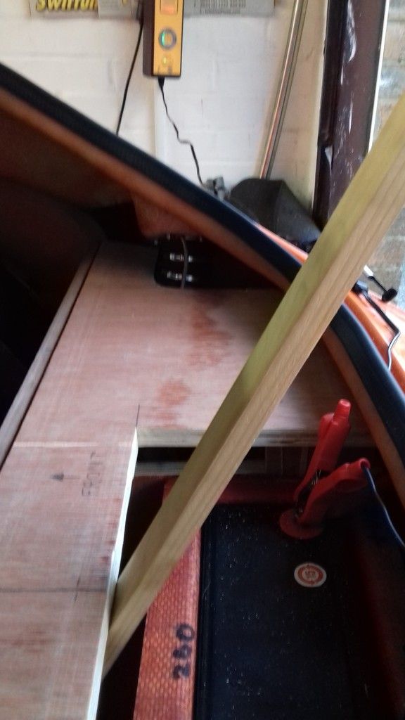
This piece is a template (funny old thing) - in making this it became patently obvious I don't need the cut out for the battery box. Therefore the 'real' cover piece will only have a small hole (to be able to lift the cover, and to put my piece of wood hatch stay in place. |
Last modified January 14th, 2017, 21:07:40 by Graham Bichard |
|
|
|
| |
Reply: 404 - 599 |
|
|
Pages: « ... 17, 18, 19, 20, 21, 22, 23, 24, 25, 26, 27, 28, 29, 30, 31, 32, 33, 34, 35, 36, 37 ... » : All |
|
|
| |
| Forum Rules |
You may not post new threads
You may not post replies
You may not post polls
You may not post attachments
|
HTML is on
Blah Code is on
Smilies are on
|
|
|
|


 Mini Marcos Forum > General Boards > Mini Marcos > Right - join Part A to Part B etc, etc, etc


 Logged


